
Last Autumn, I began the process of building a chicken coop and chicken run for about 4 chickens. One of the biggest concerns for me was making sure that the door to the coop is secure at night. There are plenty of expensive automatic coop doors available online, but I was more intent on building my own door because ... uh... well.... I like to build things.
Enough jibber jabber, let's get to it!
The Door
Mounting the motor
 For opening and closing the door, I am using a 12 volt automobile antenna
. My original plan was to make the door open vertically, but after a few tests, I opted for a horizontal sliding door design.
In the vertical orientation, is was common for the door weight to make the gears jump in the motor and then the door would come crashing down. I want a door, not a guillotine!.
Push/Pull Mount for the antenna
 Much like the mounting brackets for the motor itself, the antenna is connected to the door using plumber's tape. Yea, it looks rather janky, but it is solid and it works.
Opened and Closed


On the top left and right of the sliding door, are magnetic switches that are used to register when the door is finished opening or closing.
A bar of soap was rubbed in the channels where the door will slide, in order to make for a smooth operation.
There is a gap in the door track (visible in the bottom left). As the chickens go in and out of the coop, the track will accumulate straw and droppings that may cause problems with closing the door all the way. By leaving a gap in the track, accumulated gunk will get pushed out of the way when the door closes.
Making A Case For The Controller
The coop door is controlled by a BeagleBone Black running Debian Linux.
Gather some supplies

- a ceiling lamp for the recycling center
- some j-b weld
- a beaglebone black
- a DPDT 12 v relay
- a 2 channel relay
controllable via IO pins on the BeagleBone.
- some of those stand-off thingies I like so much
TAKE IT APART!
 Sadly, this is the only part of this build where I get to take something apart.
All of the electronic internals were removed from the lamp.
Weld things in place
 The relays and beaglebone black were mounted to stand-offs and then j-b welded in place.
The hole in the bottom of the lamp base will be used for routing wires and cables.
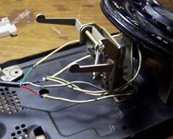
Route some wires.
 There are 5 wires coming from the coop door that need to be routed into the shed where the controller will be mounted. One wire for each of the magnetic switches, the common ground for the switches, and two wires for the motor.
Mount it!
 Here is the 'lamp' with the cover in place. Originally, I had hoped that I could use a USB WiFi adapter for the BeagleBone to access the network but the distance was too great. Instead, I configured a spare router running DD-WRT to act as a repeater bridge and the BeagleBone was networked to the repeater.
A 12v 6a power adapter was wired to the relays in order to send 12 volts of power to the antenna.
Platform and ramp
 After the door was finished, a platform and ramp to the chicken run was added to the coop.
Now it is time to get some birdies! bok bok bok!
Why did I use GNU Linux when I could have used a microcontroller with a light sensor to control the door?
I used Linux as the basis for my door because I wanted to use skills and tools that I already know, and I like having choice when it comes to programming languages used in my projects... and the light sensor doors are all fine and dandy until those sneaky no-good raccoons get their hands on a flashlight!
Now quit reading, and go make something.
See also: http://www.jezra.net/blog/The_magic_starts_at_330AM_a_coop_story to see how the coop gets open and close times from the interwebs
Not too long about I built a tubular music thingy, and while it is nice and fun to play, I really wanted to automate the playing of some tunes as well as giving myself the ability to play certain tunes at certain times.
To be fair, this was the plan all along and I'm calling this thing "Spiel", which I guess is short for glockenspiel.
Before the tubular music thingy was built, I came up with a fairly plain-text music notation format that I call SMN: the Spiel Music Notation format. In a nutshell, SMN files start with "tNUMBER" where NUMBER is the number of beats per second, and then there will be a series of notes: G a b c d e f g, and rests: r. Both notes are rests will be considered whole notes unless followed by a number.
For example, Sudo Modprobe in SMN would be:
t30
a4 G8 a4 G8 a8
b8 c2 e4 d2 r8
e4 d8 c8 d8 c8
d8 c8 b8 a4 G8
a4 G8 a8 b8
c2-8 b8 G1-2
On To the Build
For the automation, I used the following:
- BeagleBone Black - for running the code, network access, etc
- 8 12V 1A solenoids with a 10mm stroke - for striking the tubular bells
- 12V 6A power adapter - for powering the solonoids
- 8 channel 5V Relay - for sending power to individual solonoids
- Cheapo USB wireless adapter
Stand Offs
 What are these things called? I don't know.
What I do know, is that once the spiky bits are bent down, these things make amazing stand offs for just about any computer build.
Mount the computer and relay board
 After the stand offs were put on the Beaglebone Black and the 8 channel relay, the stand offs were hot glued to the frame of the Tubular Music Thingy.
Place the solenoids
 More hot glue was used to place the solenoid bell hammers.
When the solenoids are energized, they produce heat, and if they stay energized long enough, they get hot enough to melt the glue.
This led me to write a script called 'heat' that will heat up a solenoid so that I can realign the hammer for a better sound.
Wire it up!
 The Beaglebone was wired to the relay (I later changed the beaglebone to relay wiring).
The relay is wired to the solenoids, and the 12V power adapter was spliced into the relay and common ground of the solenoids.
Plug it in and run some code
 Here is the finished product, ready to be played, or automated over the network.
What about some code?
The code for controlling Spiel is available at https://gitorious.org/spiel/spiel The documentation is non-existent, but there are a few .smn files in the SMN directory. If you have any questions about the code, send me an email and I'll help as I can.
My last Linux Outlaws related script
The final episode of the Linux Outlaws is nearly upon us, and I needed a script that will check if the last episode has been released, and if so, trigger the Spiel device to play the Sudo Modprobe melody.
Basically, this is a Final Episode Alarm
import urllib, time
from xml.dom.minidom import parseString
url = "http://feeds.feedburner.com/linuxoutlaws-ogg?format=xml"
#we need to loop for a while
looping = True
while looping:
#read the URL
f = urllib.urlopen(url)
xml = f.read()
#parse the XML
obj = parseString(xml)
#get the first item
item = obj.getElementsByTagName("item")[0]
#get the title
title = item.getElementsByTagName("title")[0]
ttext = title.firstChild.nodeValue.encode('utf8')
#does the title contain 370?
if "370" in ttext:
f = open('play_smn','w')
f.write("sudo_modprobe.smn")
f.close()
looping = False
print time.strftime("%Y-%m-%d %H:%M:%S", time.localtime())
#sleep for 5 minutes
time.sleep(300)
So now, within 5 minutes of the final episode being released, my Spiel device will play:
- Tags:

- Hardware
- beaglebone
Cronos!
Not too long ago, I received a Minnowboard Max, the dualcore 1.3Ghz model, and it is a sweet bit of kit.
Hear is my quick review of the hardware.
Good
A power button!
Every time I shutdown an SBC like the Raspberry Pi or Beaglebone by pulling the power connector, I cringe and hope I don't mess up the file system. Thank you Minnowboard Max for the graceful shutdown.intel graphics
A graphics chip with Open Source drivers maintained by the chip manufacturer? yes please!x86 processor
Apparently this makes #2 possible. Well not really, but there don't seem to be any other SBCs that have an Open Source driver for the graphics chip that are not x86 based.SATA connector
at some point, it would be great to add copious amounts of storage to this SBC
Bad
No OS images are available with a kernel that has GPIO enabled. To be fair, this is not the boards fault. On a side note, I tried to compile the 3.16 kernel with GPIO and PWM support but I ended up borking something. No surprise there. /me is horrible at compiling kernels.
UEFI in the firmware. bummer. This isn't as bad as it sounds either, although it is slightly more complicated than "install boot media and power up the device". Personally, I would love to skip UEFI and let the underlying BIOS handle all of my startup needs.
wow. how phenomenally indepth. :)
So what did I do with it? I'm glad you asked....
What I did with it
First, I tried to install Arch, but I couldn't get the /etc/fstab to properly recognize the /boot partition that had the UEFI boot jibberjabber on it. Can I blame this issue on UEFI? Does it have something to do with the UEFI requirement that the boot partition is formatted FAT32? Does that mean I can blame Microsoft as well? Does it matter that I was installing to the Micro SD card?
we may never know. Perhaps I was too hasty to give up, but I was itching to create, and not to debug.
Following the instructions at elinux.org, I installed Debian 8 (jessie) using the AMD64 netinstall image and then began installing the packages that I needed for compiling software and running scripts. A USB soundcard and an 802.11n wireless card were collected for the build. Then I put shit together.
Make A Case
For the most part, I recycled the case from the horrid Odroidx computer.
Suspend the board
 zip ties, yarn, and small eye screws make great stand-offs.
Here is the USB card with small speakers connected to it. A sweet microphone was later added to the mix.
Bend some metal
METAL!!!!!
 This is part of the sheet metal that was donated to me by the recipient of windchime #3. Thanks Buddy!
What you are looking at is a microphone holding bracket screwed to the wall.
Microphone check! one two one two

Oh my, is that a sweet rewired mic that I see there? yes, yes it is.
Did I mention that I reused a lot of projects in this project?
On the wall!
 There she is: Cronos, right next to the "music room".
Recycling projects made this a bit of a breeze. The toughest part was wiring the electrical outlet behind the case so that I wouldn't have to expose any wires. keeping it clean. BOOYAH!
Software
A build is fine and dandy, but what is it running, and what does it do?
Chime the hour
Every hour, on the hour, cron runs a fairly simple Ruby script to play a "chime" for each hour of the hour. The cron code looks like
And the ruby script is:
#where is the chime?
this_dir = File.expand_path(File.dirname(__FILE__))
chime = File.join(this_dir, 'chime.ogg')
vol = 1.0
hour = Time.now.hour
if hour > 22 or hour < 7
vol = 0.1
elsif hour > 21 or hour < 8
vol = 0.4
end
#what command plays the audio?
play_cmd = "gst-launch-1.0 playbin uri=file://#{chime} volume=#{vol} &"
puts play_cmd
hour -=12 if hour > 12
hour.times do |i|
system(play_cmd)
sleep 2
end
And the chime audio is a recording of low note from wind chime number 2 with the pitch shifted. Hey! Where is the video of windchime 2?
Text to speech
Thanks to the USB sound card, the computer has audio out other than through HDMI.
For converting Text to Speech, I am using festival with Arctic voices.
Aside from the system itself using festival for text to speech, I am also running a modified version of my ruby webrick based web server for text to speech that uses festival and allows me to send text to speech commands to the computer from any network connected device.
I should mention that although the Minnowboard Max is a fairly speedy little computer, festival text to speech is quite the resource consumer and there is a delay between when a request for speech happens and when the resulting audio is actually heard. This lead to a feature in Blather.
Damn it computer! Do what I tell you!
Blather handles all of the voice commands for telling devices on my network what to do.
Because I needed some sort of instant feedback for whether Blather accepted my voice command or not, an option was added for running a script when a valid voice command was detected. Similarly, an option was added for running a script when an invalid voice command was detected.
In this implementation, the "valid script" plays an "affirmative beep" and the 'invalid script" plays a "negative beep". Since no one offered to help me with the audio, I busted out my cheapo USB mic and recorded my own files. :) oh man....
Affirmative: bing!
Negative: booduhbooduh
Well there she is. Now if you will excuse me.... "Play Iron Maiden"
After putting together the rotary phone beaglebone machine, I decided that I still needed to do something with the extra pinouts on the beaglebone. Since I had recently started using MyTinyTodo to keep track of my todo list, I thought it would be nice to have a quick visual display of how many things are still on my todo list.
To Accomplish this my goal, I would need to add some LEDs to the beagle bone and then hack some code to do what needs doing. First thing first: add the idea to the todo list.
Gather Some Components
 In order to get this project going, a trip to the nearby electronics store was in order. After returning home with 10 green LEDs ( the plan was to use 6, but I figured buying extra would let me fry a few), I realized that there was a lack of 100 Ohm resistors in my home.
Fortunately, I had some 50 Ohms that I soldered in series to handle the job.
This is a very boring pictures; don't look at it.
Solder 6 of These
 This is the basic circuit that get's wired to the BeagleBone. The extra length of wire will get cut off and the entire thing will be wrapped in a bit of electrical tape.
While I was at the electronics store, I bought some fans to replace the fans in the clock server because I think it runs too hot.
The Finished Circuit
 Well looky looky! The circuit is finished. Six LEDs with a common ground, with a 100 Ohms of resistance for each LED.
Time to wrap these babies up with electrical tape and hot glue them into the BeagleBone's case.
Glued in Place
 On the third attempt, I managed to almost get the LEDs glued into place where I wanted them. Yea, it took me a few time of gluing, and then prying the LEDs from the case a regluing before things were working properly.
As it is, one of the LEDs still doesn't let the box close very easily. Terrible terrible design. That's it! I'm firing myself.
Oh hey! This is probably the best picture that shows off the flowers etched in the glass.
7 Things On The ToDo List
 At the time this picture was taken, there were 7 things on my todo list. But there are only 3 LEDs lit up. That's right, the LEDs need to be counted in binary from left to right.
With this setup, using 6 LEDs, the ToDo List will max out at 63 items; and I if I have that many things to do, something is very wrong.
Every 5 minutes, the LEDs run a simple animation sequence, parse the ToDo List RSS feed and then turn on or turn off LEDs as necessary.
Since there is still plenty of room in the box, I'm thinking of adding another something-or-other that is controlled by the BeagleBone pins. I'm not sure what it will be, but I can guarantee I'll have fun making it.
Hack on!
PS. I really want to have 15 things on my ToDo list, just so I can say "THERE...ARE...FOUR...LIGHTS" Ha hahahaha, I crack me up.
Rocking the Rambler
 Remember the dash of my buddy's 1966 Rambler from http://www.jezra.net/blog/The_Wrench? Well, that dash has a stock AM radio that looks really nice. Unfortunately, there aren't very many AM radio stations in the area that play music worthy of listening to in a 1966 Rambler. So, for my buddy's birthday, I decided to make an AM transmitter that would deliver music of his choosing to his radio in sweet sweet monophonic sound.
Schematic
 A quick internet search for "simple AM transmitter" let me to http://justtechnika.com/articles/circuit-diagram-simple-digital-am-transmitter/, which seemed to be exactly what I needed. About $5 later, the components needed to make three of these things were on their way to my home from digikey
After a few minutes of figuring out where things needed to go, I had a working prototype on a development board. I accidentally left out the 1000 micro farad / 25 volt capacitor. Oh well, it still works.
Test the prototype
 The first test of the prototype took place with my alarm clock AM radio and I really needed to test this on the real thing.
Hey Buddy, bring your car over here!
The transmitter worked like a charm as long as the transmitter antenna was touching the radio antenna. (this is a good thing)
The real deal
 A month or so after I started this project, I had a finished circuit ready to deliver to my buddy and a small burn on my finger. Damn soldering iron. The finished product is about 5x3 centimeters in size and a power switch has been added.
Hopefully the circuit doesn't sit around his apartment gathering dust.
hint hint
Hey Buddy! We should hella install that transmitter this weekend
When this gets installed, we are planning to connect the transmitter directly to the antenna where it plugs into the radio.
A bit of Computer Repair
My good buddy Constance has a rather old computer. Actually, it is an original ibook with a speedy 300Mhz processor and a whopping 192M of RAM.
OK, the RAM has obviously been updated, but other than that, the computer is still original.
One day, Constance told me a tale of tripping over her computer cord and then the adapter started sparking. Crap! The machine may be crap, but it is all she has and it has all of her writings on it.
 Ah, the slow as dirt machine. See that "yo-yo" power adapter? Aside from always burning out, those things are $80 from Apple. I'll be damned if I let Apple get any of my poor writer friend's money. Let's fix that shit!
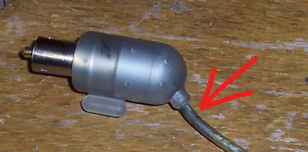 First thing first: find out where the cord is fried. Well, I'll be damned, it just happens to be fried where every other "yo-yo" adapter gets fried.
(That's me being sarcastic)
 It went like this:
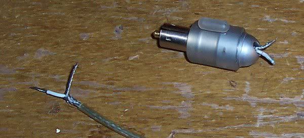
1. cut off part of the plastic housing
2. cut and strip wires
3. determine that the amount of exposed wire is to too short for my pathetic soldering skills
4. cut off all of the plastic housing
5. discard the metal housing under the plastic housing
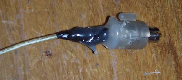 Hit it with some magic!
After soldering the wires, I used hot glue to re-attach part of the plastic housing and then I wrapped the wires with electrical tape. Just to be save, I slather on a crapload of hot glue to keep everything together.
Solder, electrical tape, and hot glue. Shazaam! That's three adhesives in one project!
When the repair was completed, I put the machine in bag and pedaled over to Constance's house, where I was greeted ecstatically. It should be noted however, that there was a serious lack of cookies/coffee/beer/scotch waiting for me when I got there. cough cough, cough cough cough, hint hint.
Now quit reading, and go repair a crappy 11 year old laptop.
P.S. If anyone has an old laptop gathering dust, and the laptop isn't as crappy as Constance's current piece of shit, let me know. (Constance really needs an upgrade)
She will make some cookies when you tell her which kind.
(Are Tacos a cookie? )
seriously
The connector port cracked on the inside of the laptop case, so I took it apart and soldered in some braided wire that exits the chassis. Then I put a phoenix connector on the end. I then snipped off the end of the power adapter cord, and wired it into a phoenix connector also.
Works perfectly now. Common problem due to the stress on that connector or something.
I had to solder it back on, and then tape it in place because the solder points would be the only thing holding it in place otherwise. It sorta works now, but you have to be ginger with it.
As for newer laptops: I don't have anything past the Pentium I era that functions (and most of those don't function, either), but I'll make sure to keep my eyes open.
@windigo, perhaps you should invest in a hot glue gun to help keep things in place.
One can never have too many adhesives
My kids removed the down arrow key and the 'n' key, I think, but it all works fine.
(jamba, put linux on it and give it to him for free. picture it as a donation to the cause. ;) )
@nybill, I think I'm about to install freeBSD on it, but I'll think about it :-)
ah, and now I think my desktop is busted.... I think the north bridge melted or something. dangit.
Step 2: write "n" on the square
Step 3: glue the square to the keyboard
done!
turns out...my north bridge is definitely burned/burning up. when it rains, it pours
 The tag on the phone said:
phone
as-is
$8.50
Perfect.
In various states of functionality, there are about 15 rotary phones in my home, this particular phone however, is destined for a different sort of communication.
Based upon the schematic that was used for the serial switch project I really wanted to make a multi-switch input device. It would be easy to simply solder on two more switches to the existing project and then run various commands when each switch is pressed, but that wouldn't be much fun. Fortunately, I know that a rotary phone has three switches inside. Let the fun begin.
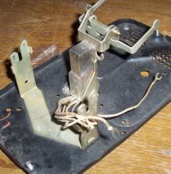
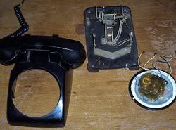 The phone was light, too light. From experience, I had guessed that the ringer was gutted from this phone. Not only was the ringer gutted, but most of the internals where also removed. Oh well, it makes things easier for me. Here you can see the body, the internal cradle switch mechanism, and the back of the dialer.
Perhaps I should do this with every phone I have with a missing or broken ringer.
 Step 1. Determine which of the wires coming from cradle switch from a closed circuit when the headset is placed on the cradle. There can't be more than 8 wires so it should be fairly easy to do.
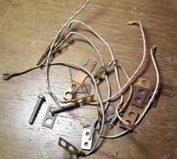 Whoops. Wow, those things fall apart fairly easily and I was left with a pile of wires, switch contact points, spacers, and a sense of determination.
This is about 75% of the wires.
 Hey, that wasn't too hard to put back together. Much like the toys I insisted on taking apart as a child, this switch was put back together with a few parts missing.
Actually, I only needed two contact point to make the switch work the way I want it to. The extra contact points were added to give pull on the slotted bar connected to the spring lever.
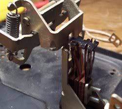
 This is a close of up the back of the rotary. There are two switches here that I will refer to as the rotator and the dialer. If the rotary is moving then the rotator switch is making a closed circuit. The dialier on the other hand is normally closed, but when the rotary is swinging back to its default stationary position after a user has dialed a number, the dialer switch will break the circuit a number of times equal to the number that was selected. After the rotary has finally parked in the stationary position, the rotator switch opens and breaks the circuit.
 Three switches means 6 connections: 3 grounds and 3 leads. Since the three grounds will be soldered to the same pin on the serial port, I only need a 4 wire cable. Fortunately I had a spare black USB cable( and USB cables only have four wires).
All soldered up and ready for electrical tape. OK, I used duct-tape.
 All done with the hardware, now it is coding time!
Fast forward an hour
The code is done and everthing is working as expected. So how does it work?
1. pick headset off of cradle
2. dial a number that corresponds with a command in the configuration file
3. hang up the phone
4. the command is run on the computer
For example:
- dialing "1" will run the command "firefox http://www.linuxoutlaws.com " which will open the Linux Outlaws website in Firefox.
- dialing "2" will play the latest episode of my favorite audcast; It is time to remove the pod and put in some aud-io.
- dialing "22" will play the Conan Soundtrack
- dialing "23" will play compositions by Basil Poledouris (randomly)
- "3" will quit all audio players
- "01189998819991197253" will run "firefox http://www.youtube.com/watch?v=RK4Xye7AErE "
quit reading and go make something.
On the Linux Outlaws Podcast, there is a feature on the show called the "crap alert"; which is an alarm sound that plays whenever Fabian, one of the show hosts, states that something is crap. There were a few discussions on the show's forums regarding playing the alarm on one's own computer.
"Hey, I have a switch and I want to use it to play a command on my computer!"
But how do I do it?
A bit of research found www.swen.uwaterloo.ca/~drayside/altinput/, which has information regarding making a switch to connect to the serial port of a computer. After a bit of soldering, my serial port switch was complete. All it needed was some sort of driver. Having previously worked with Python to access data from a serial port, I decided to use Python to poll the state of the switch and run a command when the switch is depressed.
Here is the "driver"
#!/usr/bin/env python
import serial
import gobject
import os
import sys
import subprocess

class serial_checker (gobject.GObject):
    def __init__(self):
        self.config = {"port":0,"carrier_detect_pressed":"echo carrier\ detect\ pressed\n"}
        #read the config file
        cfile = os.path.expanduser("~/.serial_switch" )
        file_lines = open(cfile)
        for line in file_lines:
            #trim the white spaces
            line = line.strip()
            #if the line has length and the first char isn't a hash
            if len(line) and line[0]!="#":
                #this is a parsible line
                (key,value) = line.split(":",1)
                self.config[key.strip()] = value.strip()

        self.cd_switch_down = False
        self.cd_switch_action_running = False
        gobject.GObject.__init__(self)
        self.switch_count = 0
        #define our serial
        self.ser = serial.Serial(self.config["port"])
        self.mainloop = gobject.MainLoop()
        gobject.timeout_add(150, self.check_switches )

    def cd_switch_action(self):
        #what is the user requested command?
        command = self.config["carrier_detect_pressed"]
        #print command
        #run the command, this should be in a thread or asynchronous
        subprocess.Popen(command,shell=True)

    def run(self):
        #run the main loop
            self.mainloop.run()

    #check the switches
    def check_switches(self):
        cdval = self.ser.getCD()
        if (cdval):
            if(self.cd_switch_down==False):
                self.cd_switch_down = True
                #try to run the cd switch action
                self.cd_switch_action()
        else:
            self.cd_switch_down = False

        return True

    #when the class is closed, clean up
    def __del__(self):
        self.ser.close()
        self.mainloop.quit()


if (__name__=="__main__"):
    ser_check = serial_checker()
    ser_check.run()
When the python script is first run, it reads a configuration file from my home directory named ".serial_switch", which contains the command that I want to run when the switch is depressed. The config looks like this:
# this is a config file for serial_switch
# all configurations will be in key:value format

# serial port (default /dev/ttyS0 )
#port:/dev/ttyS0

#what happens when the carrier_detect switch is pressed
carrier_detect_pressed: gmrun
Although I played around with various commands that I thought would be fun to run when the switch was depressed, I found that gmrun was more useful than playing an audio file.
TODO
Add more switches to the serial connector.
Physically, the serial connector should be able to hand 3 or 4 switches so I should add the switches and update the software accordingly.
What it looks like
Here is the video I uploaded to youtube.
- Tags:
- Hardware
- Tubular Music Thingy Part 2
- Beaglebone console output and a faster boot
- Tubular Music Thingy (part 1)
- get and speak the weather
- Getreel youtube-dl wrapper
- Two hours with the Archos 43
- HTML5 for a specific platform? I prefer to develop native apps
- a bit of dev talk about MuttonChop media player
- case for my status server
- my tiny todo list and some ruby
- The Camp Mug (almost) Test
- 2012 Tizen Developers Conference in San Francisco
- Freedom Jar is Full
- Web UI speed up using HTML5 Server Sent Events
- LEDs, BeagleBone, and my ToDo List
- a case for the BeagleBone
- fixing the car mirror
- Basic HTTP server in Vala using GIO Sockets
- sewing up a bling thing
- Trip to Austin
- convert hexadecimal string to an integer with Vala
- Training for 2012: Wuggling
- ABC tune grabber/converter
- A trip to Lancaster
- a new media playing machine
- Don't turn Tizen into WebOS
- making some chili sauce
- grumpy kid
- beer network improvement
- Ripping my DVD collection
- ruby script to search files in a directory for a string
- Pacific Pinball Museum Mission
- A Tale of Two Mugs
- shishi odoshi prototype
- file downloader in Node.js that handles redirects
- Travelling Far Part II
- python shell-fm web interface
- not quite a letter to cherrypal
- Audio playing class in Ruby with Gstreamer
- A quick fix
- my resized images using Ruby and Imagemagick
- one pound of coffee
- noise-canceling headphones that actually work
- updating my dynamic IP DNS information with Ruby
- Hello World in Ruby
- Bacon Apple Cider
- clawhammer sudo modprobe
- a web.py introduction
- The Skillet
- banjer strap on the cheap
- The Letter to Dell
- Linux Outlaws episode 170
- Not the 2010 Petaluma Whiskerino
- Monte Rio
- a new power switch
- the coffee cup review
- seriously, that thing is garbage
- keeping a GTK TextView cursor in view
- A tale of three sticker
- minimize/close to system tray in Python GTK
- A markdown editor/viewer in Python
- Red Phone Mumble Test
- Saturday Sassafrass
- A Friday Frolic
- Toshiba laptop review
- Google no longer uses Microsoft
- regarding Heybuddy and python stuff
- I'm calling you!
- heybuddy identi.ca client
- making a change holder thing
- Did I win? Yes and No.
- photograph sticker
- share this on facebook
- the damn computer died
- kilt alteration
- audcast streamer in vala with gstreamer, gtk and webkit
- The Mullet Adventure
- A Letter to the California State Legislature
- will dogfooding the frenzy leave me bitter?
- basic sitemap file maker in Python
- rock and rolling down the street
- Time to Celebrate
- game of life : Vala, SDL
- game of life : python, clutter
- networked timed text-to-speech goodness
- battery status in a screen session
- Bright Bike
- turning gears
- incremental screenshot namer wrapper
- a nice little feature/bug
- drawing circles
- broken VHS fixed
- cloudy phone number finder
- network quitter fixer
- the hot sauce experiment
- non-delivered emails sent to AOL domains
- GIMP mathmap experiment results
- tri-force tuna gift
- leave early, take your time, enjoy the solitude
- N37°49'8 W122°28'48
- rotary phone computer interface in action
- python script to play the latest version of an audio broadcast
- rotary phone computer input device
- server log spam from Microsoft?
- creating a CAPTCHA
- hello HTML 5! a simple audio player
- How does that increase security?
- getting familiar with GWT, a porting experiment.
- You're Not Carnival Personnel!
- "disable" a web app's buttons using javascript and css
- litterbugs and jaywalkers
- a basic web-app with pyjamas
- shell script to aid in compiling Vala projects
- Banjo part 4: she's finished
- Accent Characters in Linux with Xorg
- Terminal emulator part deux!
- Community
- Terminal Emulator in Vala using GTK and VTE
- Where is the MPAA on this one?
- pyclutter stage fullscreen hack
- Banjo part 3
- from necessity comes something
- If you build it, they will spam
- writing blogging software ( using data from blogspot )
- From WBEZ Chicago......
- Simple Switch Input to Enter a Command
- perplexing ponderence, pertaining penguin presents
- baby steps: the evolution my feature-free PHP framework
- ruining a perfectly good lamp?
- thank you bazaar
- quick not-so-little bikey bag
- Vala musings : int to string, packages, and starting with main
- my motor vehicle warranty is about to expire? really?
- Bike Trailer Part 2
- getting dandy with a hair pretty
- a not so elegant fixer up
- use python and gstreamer to get the tags of an audio file
- trials with gstreamer, pygst, and goom visualization
- Gaarrrrrrrrr!
- more pyclutter: get a move on - behaviourpath
- scrollwheel css div Internet Explorer 7 problem fixed
- Hello World using pyclutter - a half assed tutorial